
Technical support
Technical support
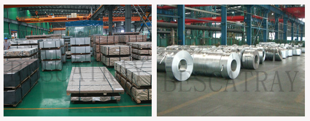
Material
Mill
Pre-Galvanized
Stainless Steel SS304
Stainless Steel SS316
Aluminium
FRP/GRP
Finish
G: Pre-Galvanized / PG / GI – for indoor use to AS1397
H: Hot Dip Galvanized / HDG – for outdoor use to BS EN ISO 1461
S4: Stainless Steel SS304
S6: Stainless Steel SS316
P: Powder Coated – for indoor use to JG/T3045
A: Aluminum to AS/NZS1866
FRP/GRP: Fiberglass Reinforced Plastics
F: Fire Rated to AS3013:2005
Z: Zinc Plated – for indoor use to BS EN 12329
E: Electrolytic Polishing – for Stainless Steel use
M: Mill / Mild /Plain Steel to ISO 4995
| Minimum Coating Thickness and Mass on Samples that are not Centrifuged (HDG) | ||||
| Article and it’s Thickness | Local Coating Thickness (Minimum)
μm |
Local Coating Mass (Minimum)
g/m2 |
Mean Coating Thickness (Minimum)
μm |
Mean Coating Mass (Minimum)
g/m2 |
| Steel>6 mm | 70 | 505 | 85 | 610 |
| Steel>3 mm to ≤6 mm | 55 | 395 | 70 | 505 |
| Steel≥1.5 mm to ≤3 mm | 45 | 325 | 55 | 395 |
| Steel<1.5 mm | 35 | 250 | 45 | 325 |
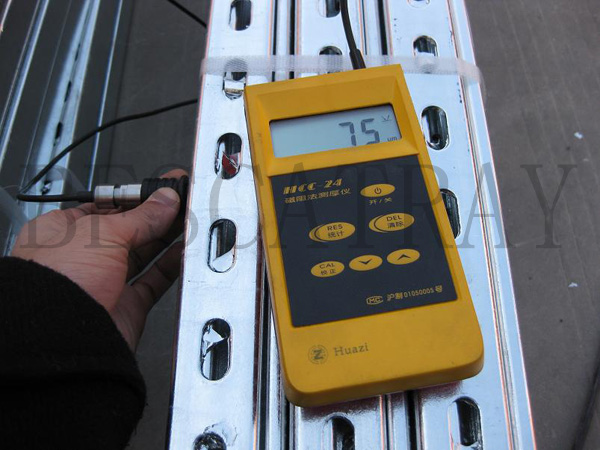
Inspection
Dimension Inspection
Coating Thickness Inspection
Cable Tray Loading Information
Load test according EN 61537:2007
Q = UDL (uniformly distributed load)
Safety Factor = 1.7
L = intermediate span
F = deflection = 1/100 of the intermediate span (max.)
S = splice location
Stated loadings apply to mild steel product only.
Besca’s load testing is in accordance with EN 61537:2001. In practical terms this covers continuous/multi
span installations, evenly loaded along the length of,and across the full width of the tray. The end spans in
these installations should be reduced to 0.75 of the intermediate spans.
DEFLECTION: Besca’s load and deflection figures are in accordance with EN 61537:2007, with the characteristic
deflection of Unistrut Cable Tray limited to span/100 and load figures inclusive of a safety factor of 1.7.
ACCESSORIES: To ensure adequate support, accessories should be supported locally.
COUPLERS: The loading and deflection tables for Unistrut Cable Tray assume that the couplers are located at the
most onerous position within the span (i.e. mid span). To maintain the load/deflection figures stated in the tables,
the couplers should not be located in end spans or over support locations. Straight couplers were utilized for the
testing of the medium and heavy duty cable trays. Only one pair of couplers should be used per span.
| Width (mm) | Useful Cross Section (cm2) | ||
| Light Duty | Medium Duty | Heavy Duty | |
| 50 | 5.4 | 11.4 | – |
| 75 | 8.1 | 17.4 | 35.8 |
| 100 | 10.9 | 23.5 | 48.1 |
| 150 | 16.6 | 35.6 | 72.7 |
| 225 | 24.9 | 53.7 | 108.2 |
| 300 | 49.9 | 70.4 | 144.8 |
| 450 | 75.1 | 106.1 | 213.6 |
| 600 | 95.3 | 141.8 | 285.6 |
| 750 | 119.3 | 171.1 | 357.6 |
| 900 | 143.3 | 205.6 | 429.6 |


